![]()
![]()
|
|
|
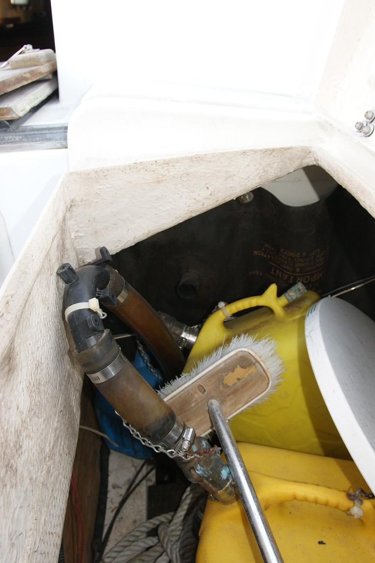
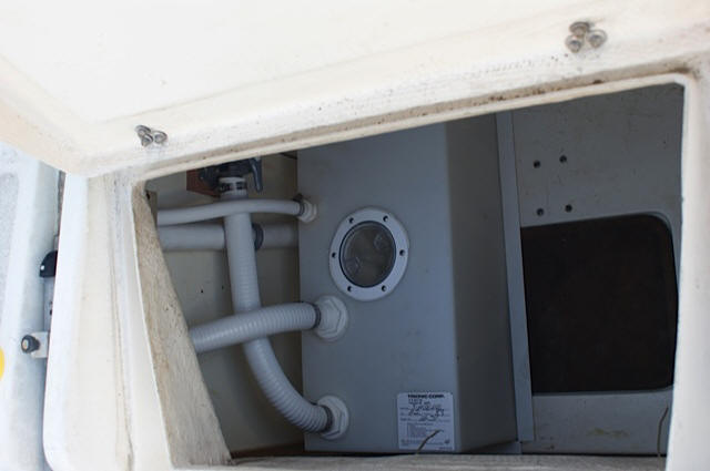
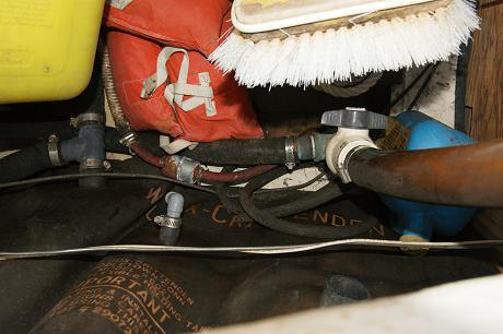
The jerry cans used for waste haul-out, showing attachment. There was so much stuff in the lazarette that it was puzzling to see how anyone would empty the compartment and then skinny down into the hold to work the hand pump.
Overview
The simple approach is as follows:
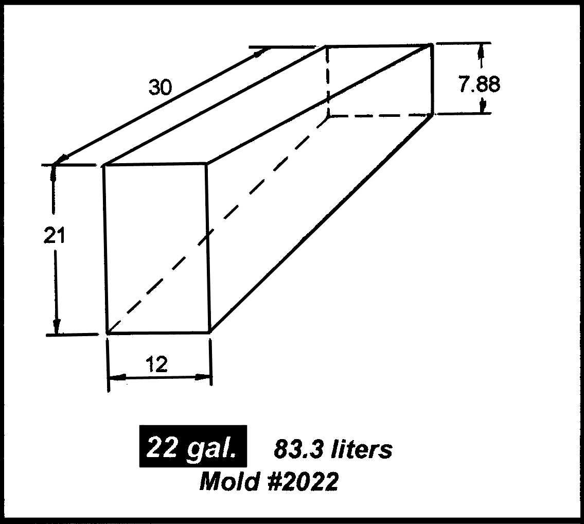
Pre-WorkWith steps 1 and 2 done, I found what looked like met the requirement,
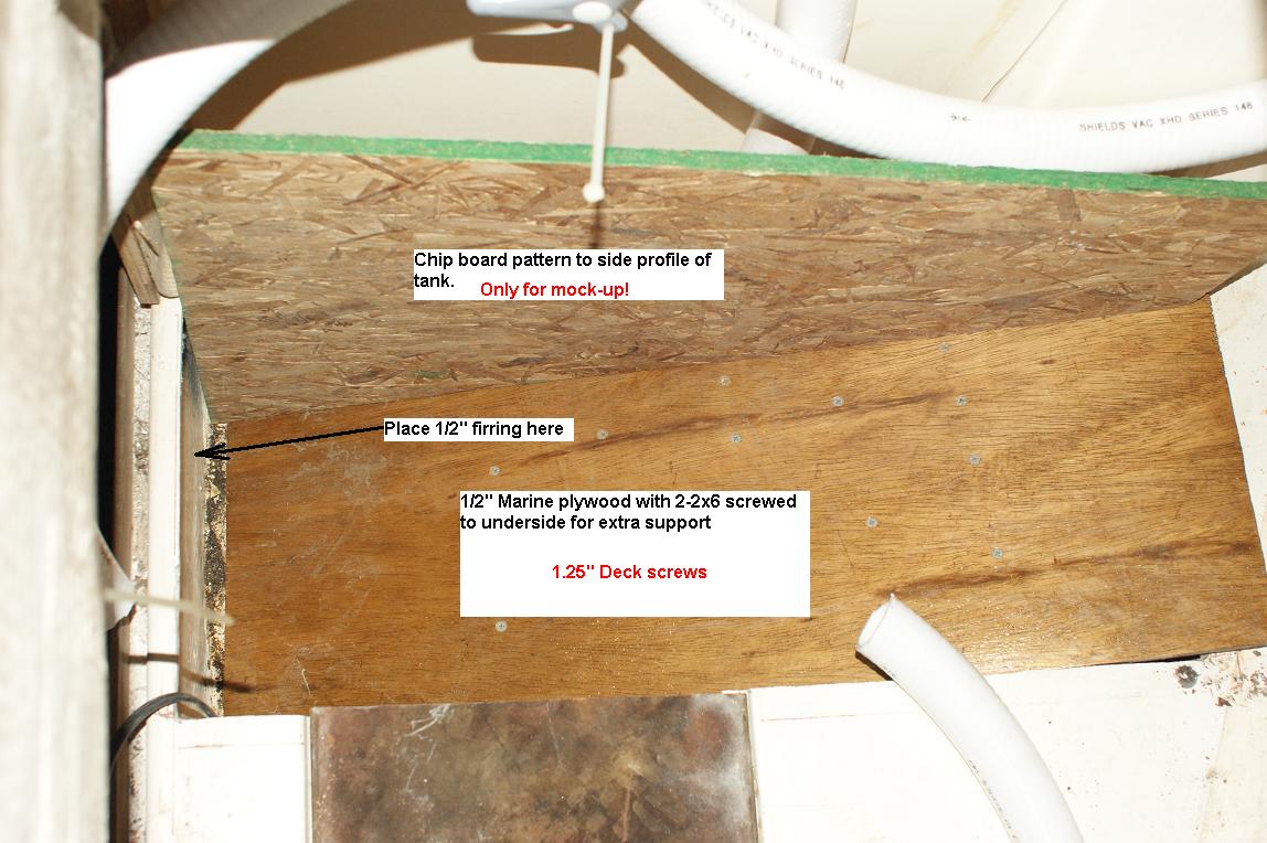
printed the spec sheets with drawing and made a mock-up. After checking
the fit of the pattern in the boat, the new tank was ordered from the
www.Tank-Depot.com for $100 dollars; Trionic model #2022. I also ordered the pump-out kit
and the fittings kit. Add shipping ($60) and you come out to about $225.
This shocked me; the shipping costs were 60% of the tank itself. I guess
since it was coming from CA or FL, was bulky and weighed a fair amount requiring special handling (sealed tanks might not fly well and need to
be shipped ground).
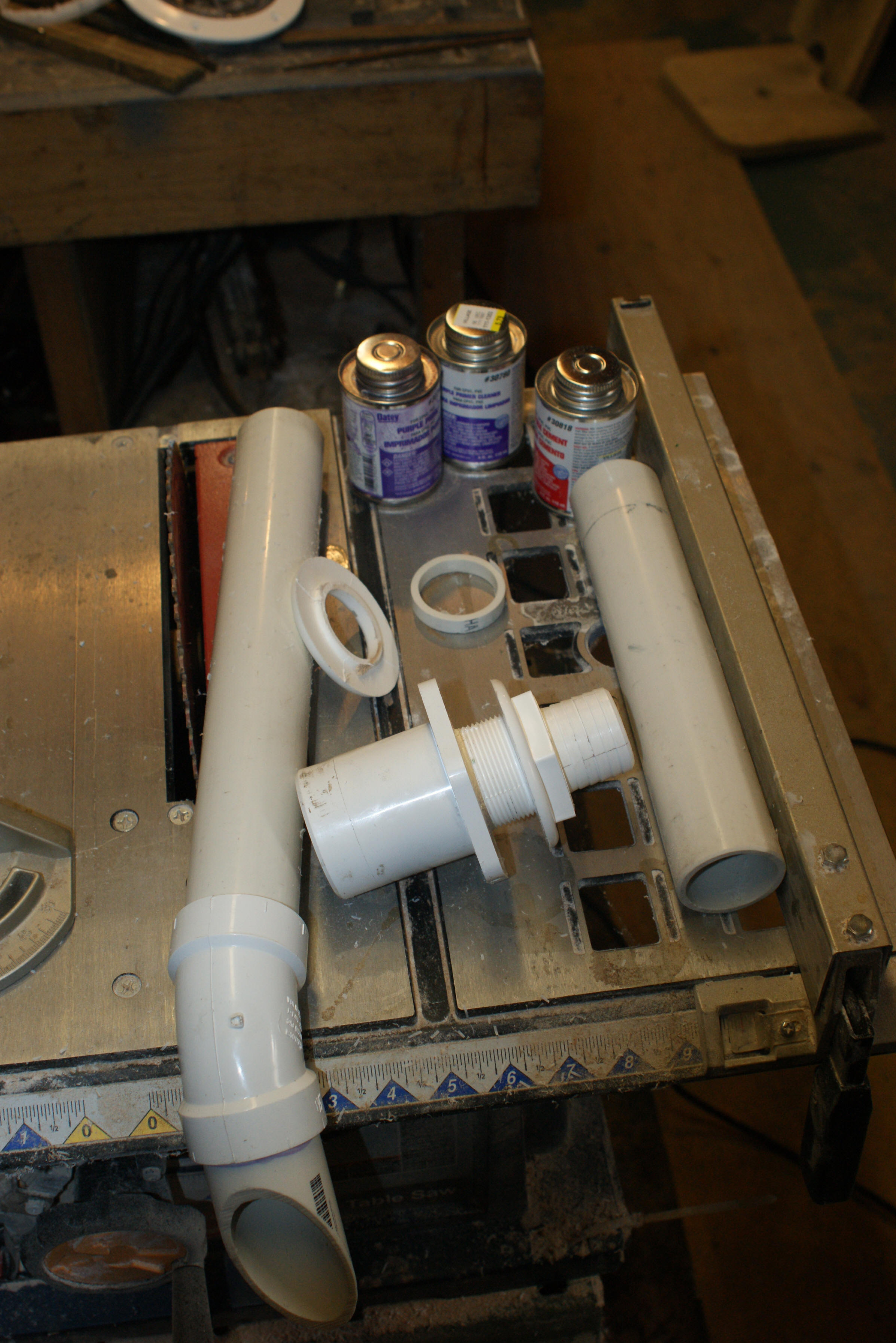
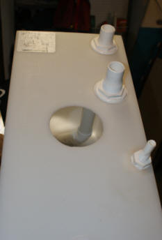
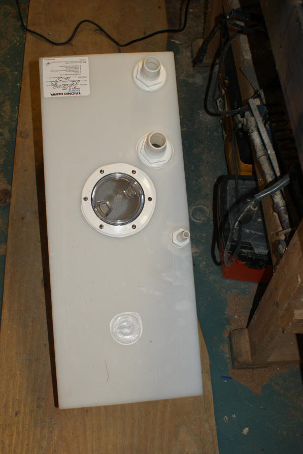
Todd Fitting Relocation Kit for Holding Tanks The new tank came completely sealed. It was ready for drilling and placing the fittings where they were needed. So the first step was to take it down to the shop and get it ready.
Having not seen the contents of the pump-out kit, I puzzled over what to do with the pieces. The design was clearly not going to work. Some modification was needed. As luck would have it, he fittings relocation kit came with 2-1.5" hose barb fittings, I cut the top (or bottom depending on how you look at it) off one of them (top leaning against the 1.5" PVC pipe). This provided the threads needed to screw into the pump-out base (the hose barb fitting is screwed into the base between the two pipes).
The inspection port was placed in the center where I cold reach the underside of the fittings while tightening. It also called for a 4.5" hole. I took out my 4" hole saw and made the initial hole. I then traced the hole-size needed from the port with a permanent marker, and cut with the Roto-Zip. All fittings were bedded with 3M 4000 caulk. It is silicone based which is recommended in the instructions. 4000 is better than pure silicone; better adhesion properties. The inspection port also comes with 6 stainless nuts-bolts-washers. It was a challenge getting the nuts started from the underside until I used the caulking as an aid; sticky fingers hold the washer and nut much better. Any excess was left to cure around the fittings.
This is the final tank prep (all of the fittings in place). It took about an hour to cut the holes and mount/bed all fittings with 3M 4000. I have several project going on in the shop at any given time, so there are a few distracting items on the floor (disregard).
InstallNow for the work down on the boat. I first marked the location of where
I wanted the tank to be located using my rafter square and a permanent marker. Being tucked up close to the bulkhead, I didn't think it would intrude on the
opening of the lazarette to much.
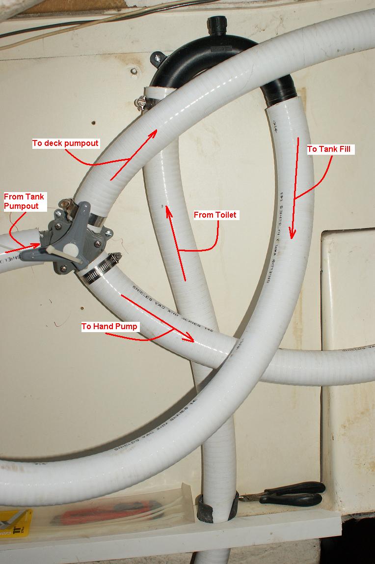
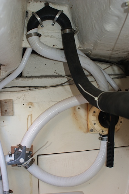
The maze of tubes and connections look a bit confusing, but that is what is
required to run from the toilet to the anti-siphon loop to the fill (bottom end
not attached since the tank is not in place). The SeaLect Y-Valve runs
between the pump out fitting and the hand pump. I still might change the
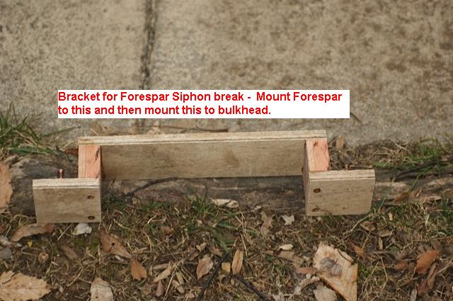
siphon break location by flipping 180 degrees (requires that I hake a new
bracket to hold the siphon break off the bulkhead). My objective was to
keep the toilet output as close to vertical as possible. The Y-Valve can
also be moved to the right if I
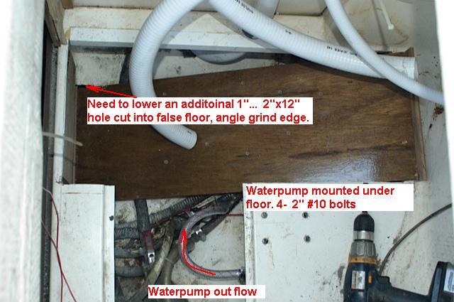
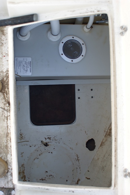
Checking the height of the pattern above the floor to the left and right, I
determined the tank had to be lowered about an 1" on the left side. This
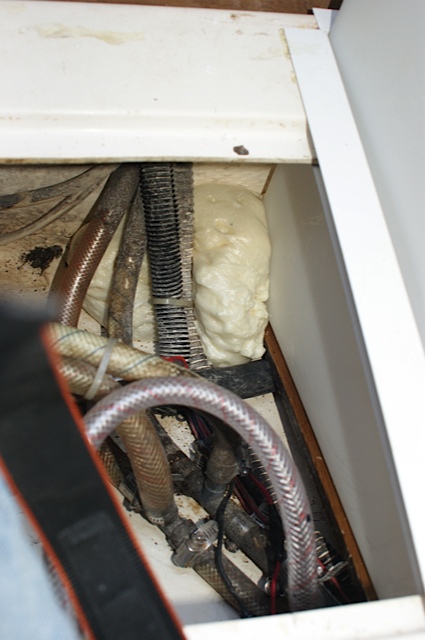
meant cutting into the false floor. It was a messy job since the chamber
below the false floor was full of nasty water. I first made a hole big
enough for a hand pump to extract the nastiness (1.5" hole saw), and poured 1/2
cup of bleach into the hole and let it set for 30 minutes. I then pumped
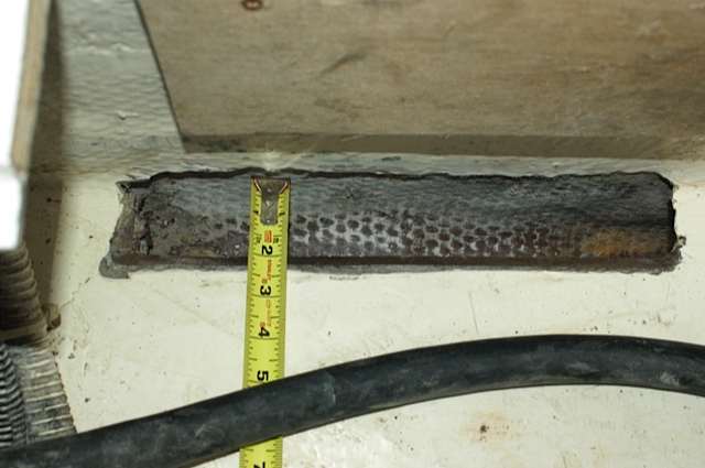
out over a gallon of filthiness and cut a 2"x12" hole. The starboard edge
was ground down with my 7" circular sander with an 80 grit sanding pad.
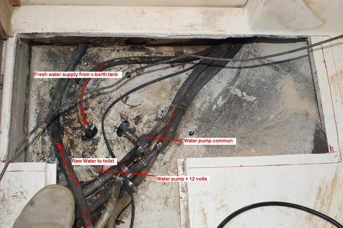
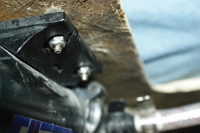
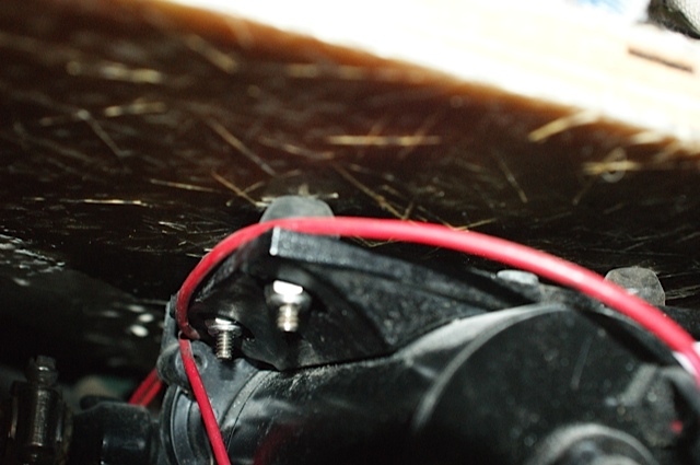
The water pump bolted to the underside of the lazarette floor. I used locking nuts (the ones with the nylon molded into the tip) to ensure they don't vibrate loose when the motor runs. This was a lot easier than I thought it would be. Just be mindful of the aft starboard corner. If you get it too far to starboard and aft, the housing might vibrate/knock on the hull when the pump runs.
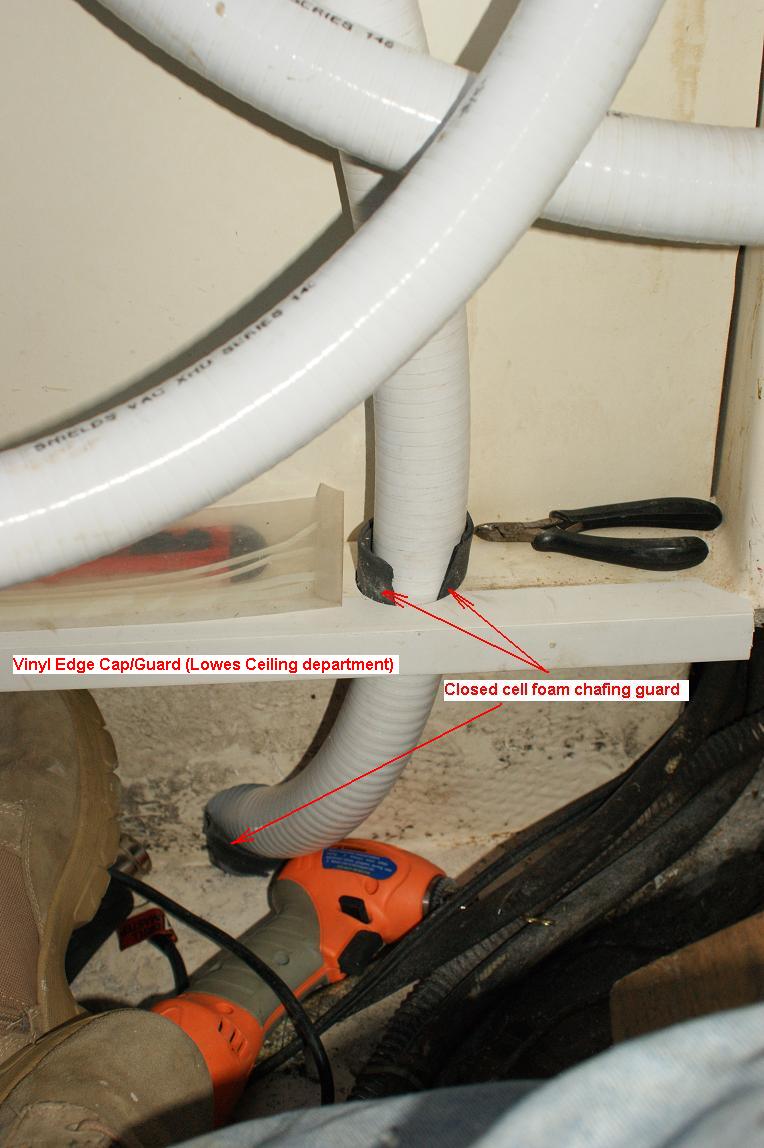
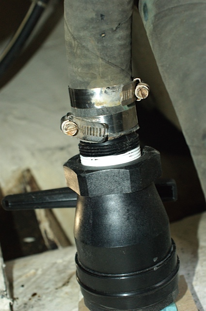
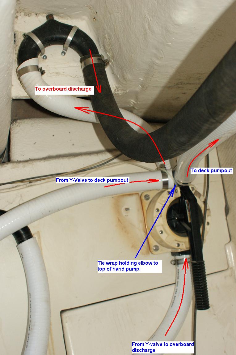
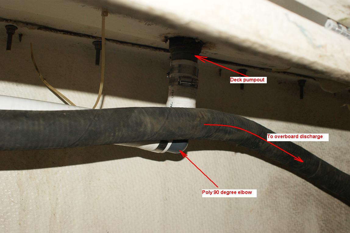
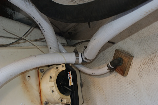
The photo to the left shows more detailed original routing of the hand pump to over-board line. I installed another anti-siphon loop here at the highest point I could find. Heating the hose up with a 1500 Watt heat gun seemed to work well for shaping the the output line from the hand pump to the siphon break. Click the thumbnail to see annotations. I used 90 degree elbows bellow the deck pump out fitting and above the hand pump. This made for cleaner runs (tighter turns) of the lines and no kinks. The water pump was relocated to the underside of the lazarette floor to the starboard of the raw water supply valve access hatch. In doing so, I did not need to extend the electrical circuits or water tank supply line. I only had to lengthen the pump output line.
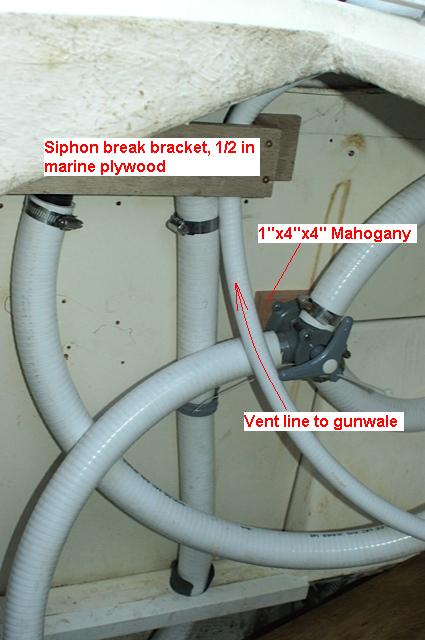
Here you see the final routing of the hand-pump lines and Y-valve. The
picture on the right shows the deck pump-out line resting on top of the
hand-pump, plus the vent line before final tightening. It is important to
keep the angle of the tube so that there isn't the down loop (the picture shows
what it should not look like). It should flow straight down to the exist,
otherwise, water could get in the line and plug the vent. Notice: the tube running from the Y-valve to the bottom of the hand-pump has sag in it. I could not avoid a swale in this line so some standing water will sit in here if I use it.
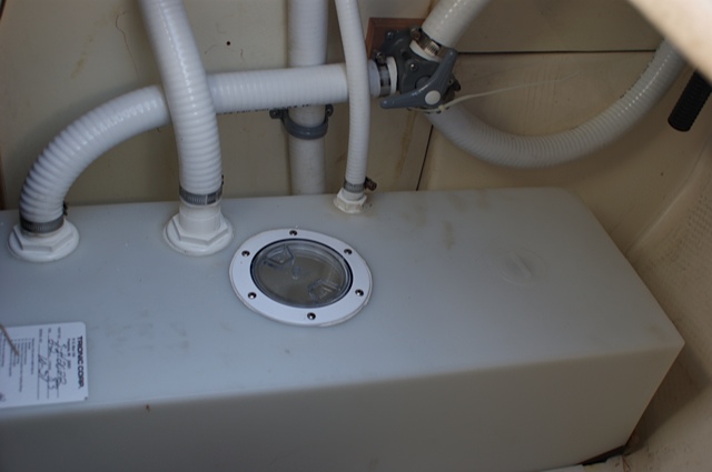
The tank fully connected at last! Testing to follow with holding tank antifreeze funneled into the raw water supply line.
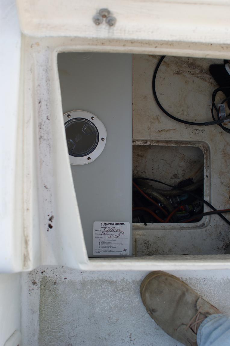
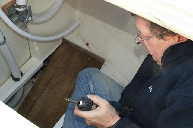
The master at work courtesy of the admiral. There is actually a lot of room down there with and without the tank in place. No problems getting in or out of the hatch and I am 6' tall and 200 lbs. The floor was scrubbed/scraped with On-Off to get the Water Heater Rust stains out (I may need to do it again). If you use On-Off down there, be sure to use a respirator designed for VOC. My wife was in the cabin and she had to leave because of the fumes while I was right next to it breathing through the respirator with no problem. On-Off is an acid and the fumes can burn the lining of you air passages. Read the caution label carefully.
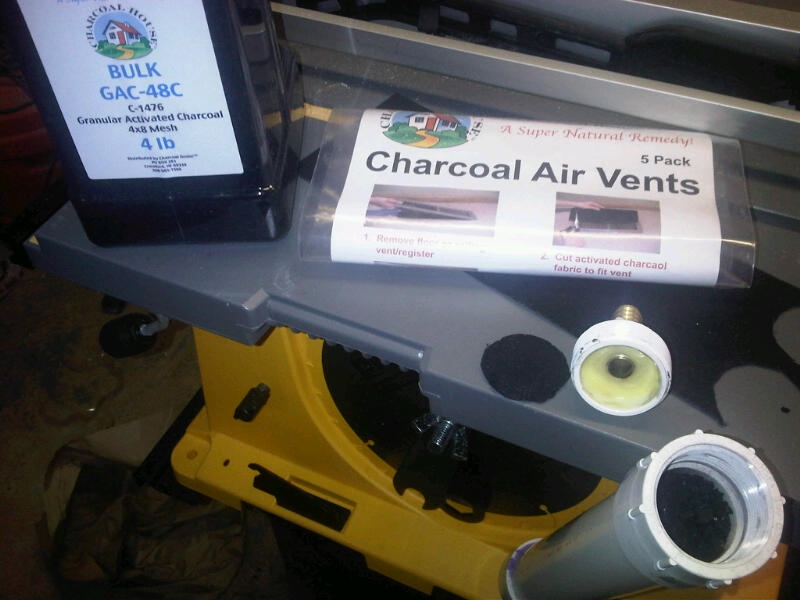
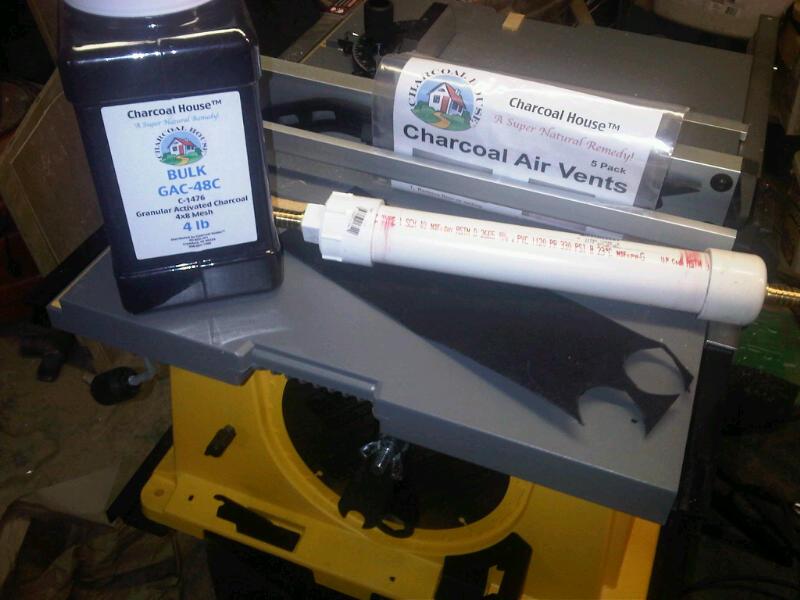
I made the vent tube filter from activated charcoal, 1.5" PVC, two 5/8" nipples, an end cap, and a removable end cap. PVC parts costs about $10. 10 year supply of charcoal cost about $43. I drilled 5/8" holes in the endcaps and epoxied the nipples in place.
|
 The
previous owner installed a pump-out system that he could direct to 5 gallon
jerry cans, overboard, or deck pump-out port. The problem was, it smelled
pretty awful and we could not bring ourselves to carting crap in 5 gallon jerry
cans to dump in the toilet. It was time for an upgrade.
The
previous owner installed a pump-out system that he could direct to 5 gallon
jerry cans, overboard, or deck pump-out port. The problem was, it smelled
pretty awful and we could not bring ourselves to carting crap in 5 gallon jerry
cans to dump in the toilet. It was time for an upgrade.