|
Battery upgrade. In looking at my battery situation and knowing how
many gadgets I intend to have in the coming months, I know I need to make an
adjustment from the two deep-cycle batteries (dated Feb 2005) that came with the
boat. So I used Nigel Calder's method for determining my daily needs to
size the battery banks. (if you do not own a copy of
Nigel's book, I highly recommend it:
http://www.amazon.com/Boatowners-Mechanical-Electrical-Manual-Essential/dp/0071432388/ref=sr_1_1?s=books&ie=UTF8&qid=1332177106&sr=1-1)
If my calculations are correct, I would need about 100-125 Ah per day. The
properly sized house bank would then be set at 300-375 Ah in capacity.
Adding 20% fudge factor as Nigel calls it, puts me between 360-450Ah of
capacity. Now actually using that much and putting that many Ah back in is
a second part of the electrical problem I will be working on, but first lets
build in the capacity from the start. So I went down to my friendly SAM's
club and bought 4 Duracell EGC2 6 volt golf cart batteries with 225 Ah
capacity each. Hooking two in series gives me 12 volts with 225 Ah, and then
putting two pairs in parallel, I get my 450 Ah capacity and a 12 volt deep cycle
system. Now what to do
with 4 golf cart batteries , each weighing 68 lbs? Here is what I did on my H33C.

The first thing is to determine the
approximate location for where they should go.
I
know the original batteries went over the shower sump, but the boxes I needed to
house the batteries would stick up over the chart table (not a good thing).
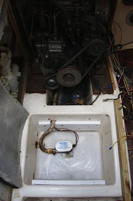
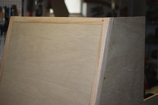
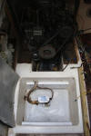
I cleaned out the sump, and lowered the support brackets as much as I could
without interfering with the bilge pump output hose. This was about 1.5"
on
Arpeggio. In the picture of the cleaned out sump-well you can see the two
screw holes on the side of the well just above the new aft 1x4 PVC support
board. Those two screws went through a 1x1 piece of teak and supported the
aft end of battery platform. With the supports lowered, I was below the chart table but still too cramped to get the
 second
box in place without tipping it over. second
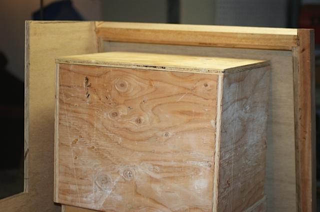
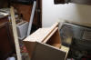
box in place without tipping it over.  So I took everything home and setup
a mock sump well and engine enclosure (already made the engine enclosure cabinet frame and walls)
and determined that I needed to lower the whole thing by another 1.75".
hmmm. (BTW - I have a new Automatic Rule 750 GPH bilge pump to install in
the well.) So I took everything home and setup
a mock sump well and engine enclosure (already made the engine enclosure cabinet frame and walls)
and determined that I needed to lower the whole thing by another 1.75".
hmmm. (BTW - I have a new Automatic Rule 750 GPH bilge pump to install in
the well.)
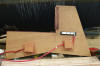
In looking at the Pro-Fill hydration
system purchased, I determined I really only needed 1.25 inch clearance from top of
battery to the
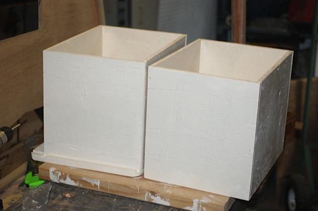
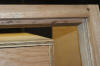 bottom to the bottom of the battery box lid. So I cut each box down so
that the space from the bottom of the lid to the battery was exactly 1.375 bottom to the bottom of the battery box lid. So I cut each box down so
that the space from the bottom of the lid to the battery was exactly 1.375 inches (1/8 inch to
spare). In so doing, I trimmed about 2.5 inches from the stacked height of
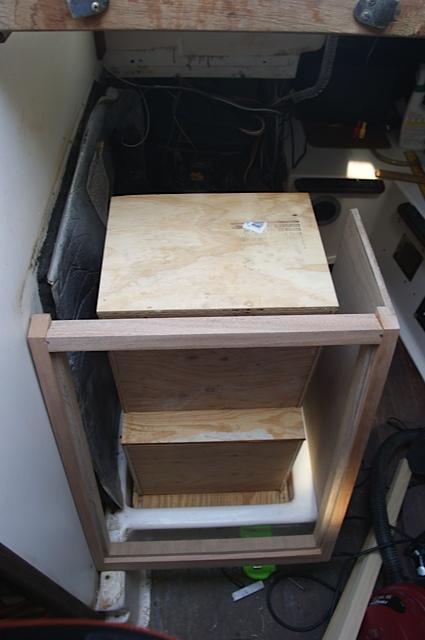
28 inches; down to 25.5 inches. This gave me the clearance I needed. I set
the second box back from the front edge of the lower box by 1 inch (the back of
the top box was back now even with the front edge of the access
opening on the port side), but this may go back a little more once I run the
cables and hydration tubes. The important part inches (1/8 inch to
spare). In so doing, I trimmed about 2.5 inches from the stacked height of
28 inches; down to 25.5 inches. This gave me the clearance I needed. I set
the second box back from the front edge of the lower box by 1 inch (the back of
the top box was back now even with the front edge of the access
opening on the port side), but this may go back a little more once I run the
cables and hydration tubes. The important part
 to this placement is making
sure my access door can still close. The internal dimensions for each box to this placement is making
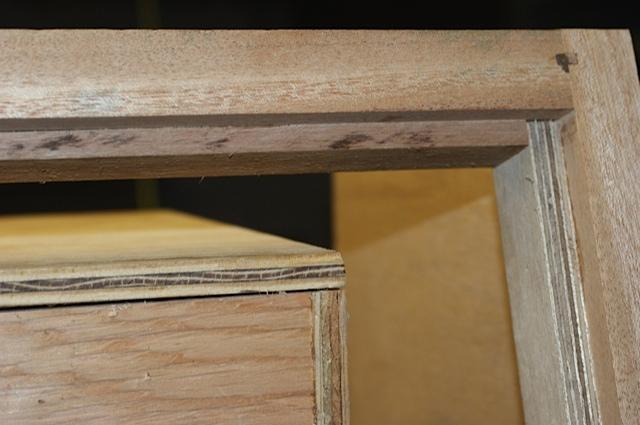
sure my access door can still close. The internal dimensions for each box are 14.25" wide x 10.375" deep x 11.625" tall. Since each lid has a 1/4"
rabbit edge, this lowers the interior height to 11.375".
are 14.25" wide x 10.375" deep x 11.625" tall. Since each lid has a 1/4"
rabbit edge, this lowers the interior height to 11.375".
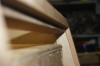
 I painted each box (inside and
outside) with Zinsser Mold Proof Interior paint tinted to the same color as Cream
Kiwigrip. All interior paint for this boat will be the Zinsser mold proof stuff.
I will use it in the head to freshen the wallpaper and engine compartment's
unpainted/unstained/non-varnished wood. (http://webapps.easy2.com/cm2/flash/generic_index.asp?page_id=35873803) I painted each box (inside and
outside) with Zinsser Mold Proof Interior paint tinted to the same color as Cream
Kiwigrip. All interior paint for this boat will be the Zinsser mold proof stuff.
I will use it in the head to freshen the wallpaper and engine compartment's
unpainted/unstained/non-varnished wood. (http://webapps.easy2.com/cm2/flash/generic_index.asp?page_id=35873803)
 Looking
good! Looking
good!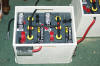 All wiring inside and outside of the boxes is 1-AWG.
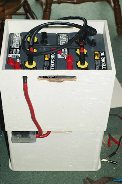
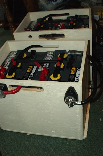
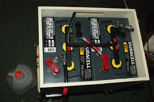
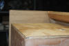
After painting, setting batteries in
each box, I connected each pair with a 5" connector. I then routed the
positive lines to the 225Amp fuse block and the negatives to a ground bus
terminal.
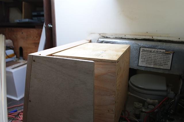
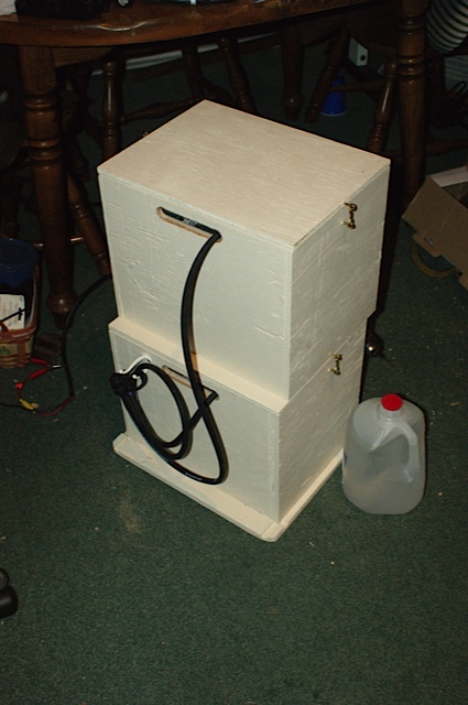
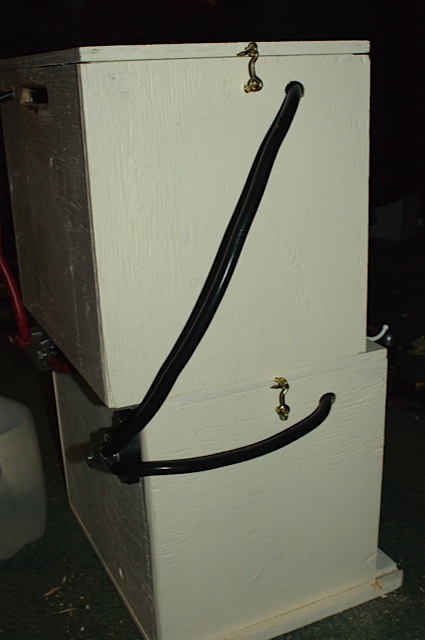
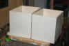
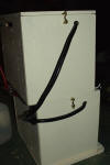
The Pro-Fill tubing can clearly be
seen here with the gallon of distilled water next to the column. The hand
pump is not in the picture (I do have it though). Everything
fits nicely and is ready to go into the boat. I secured the top box to the
bottom and the top lid to the top box with simple hook and eyes. Because
the lids of each box were rabbetted and set into their boxes, they will not
leave their box even without the hooks. I tested this to about 40 degrees
(about the balancing point). The hooks just help to keep them together.
I will secure the boxes to the sump supports when I get them to the boat and
before I load them with their battery pairs. I picked up a carrying handle
from Batteries Plus. The clerk said they don't normally sell them and gave
me one for free. How do you like that?
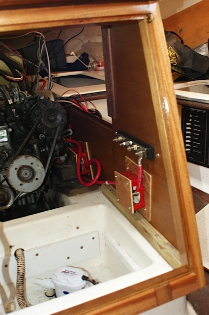
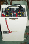
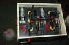
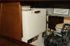
 With
the cabinet remade and assembled on the boat, she is ready to receive her new
house batteries. Note the two switches; house and starting battery
isolator switches. These are brought together by a smart charging relay
under the charging relay. With
the cabinet remade and assembled on the boat, she is ready to receive her new
house batteries. Note the two switches; house and starting battery
isolator switches. These are brought together by a smart charging relay
under the charging relay.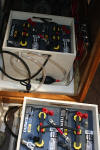
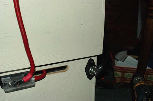
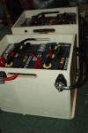
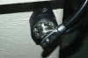
 Above
the house battery isolator switch is a 4 pole bus for taking the battery
chargers and other non-switched devices like bilge pumps, VHF-radio, stereo
memory, etc... The back of the crank battery switch has just enough clearance for between
the engine mount and switch cover plate (about 1/4"). I inserted closed
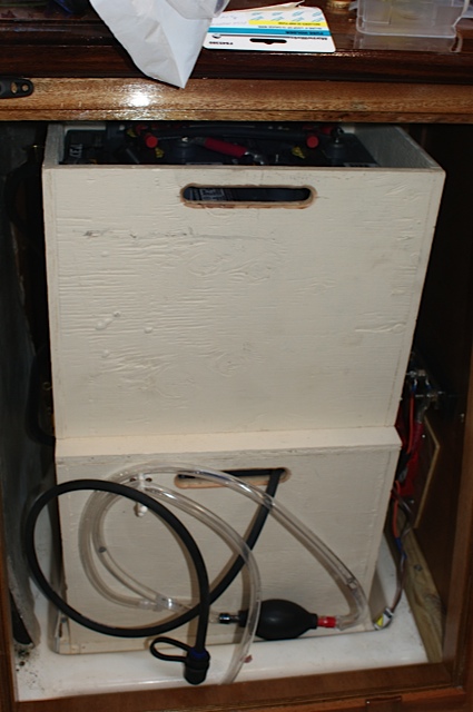
cell foam here to eliminate any potential vibrations. After muscling the
batteries up and into the boat, I loaded them in their boxes and set them in
place. The hard Above
the house battery isolator switch is a 4 pole bus for taking the battery
chargers and other non-switched devices like bilge pumps, VHF-radio, stereo
memory, etc... The back of the crank battery switch has just enough clearance for between
the engine mount and switch cover plate (about 1/4"). I inserted closed
cell foam here to eliminate any potential vibrations. After muscling the
batteries up and into the boat, I loaded them in their boxes and set them in
place. The hard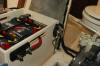 part was lifting the upper battery box and setting on the lower box.
However, taking the map table (the part that slide) out, it was actually quite
part was lifting the upper battery box and setting on the lower box.
However, taking the map table (the part that slide) out, it was actually quite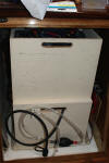 manageable. However, it would have been a lot easier with two guys for
sure.
manageable. However, it would have been a lot easier with two guys for
sure.
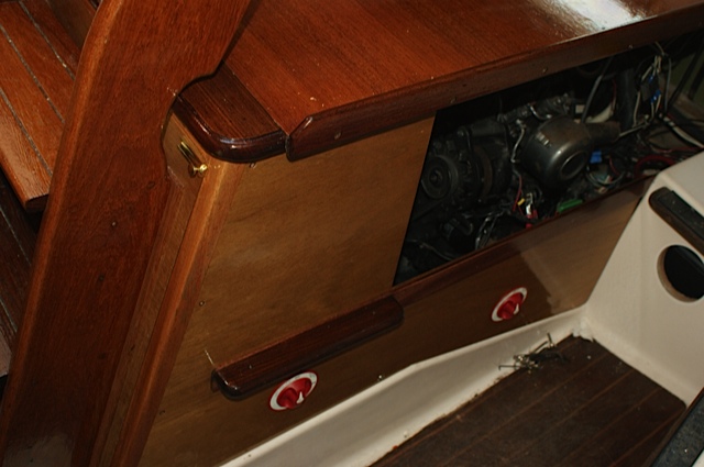
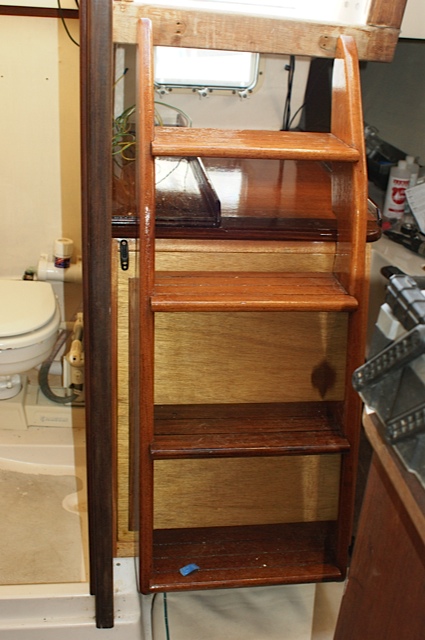
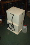
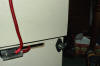
  The final assembly is shown to the left. The ladder is mounted to the
panel/door that sits in the Mahogany frame I made.
The final assembly is shown to the left. The ladder is mounted to the
panel/door that sits in the Mahogany frame I made.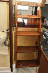 The ladder seems solid enough. It is certainly easier getting in and out
of the boat having one.
The ladder seems solid enough. It is certainly easier getting in and out
of the boat having one.
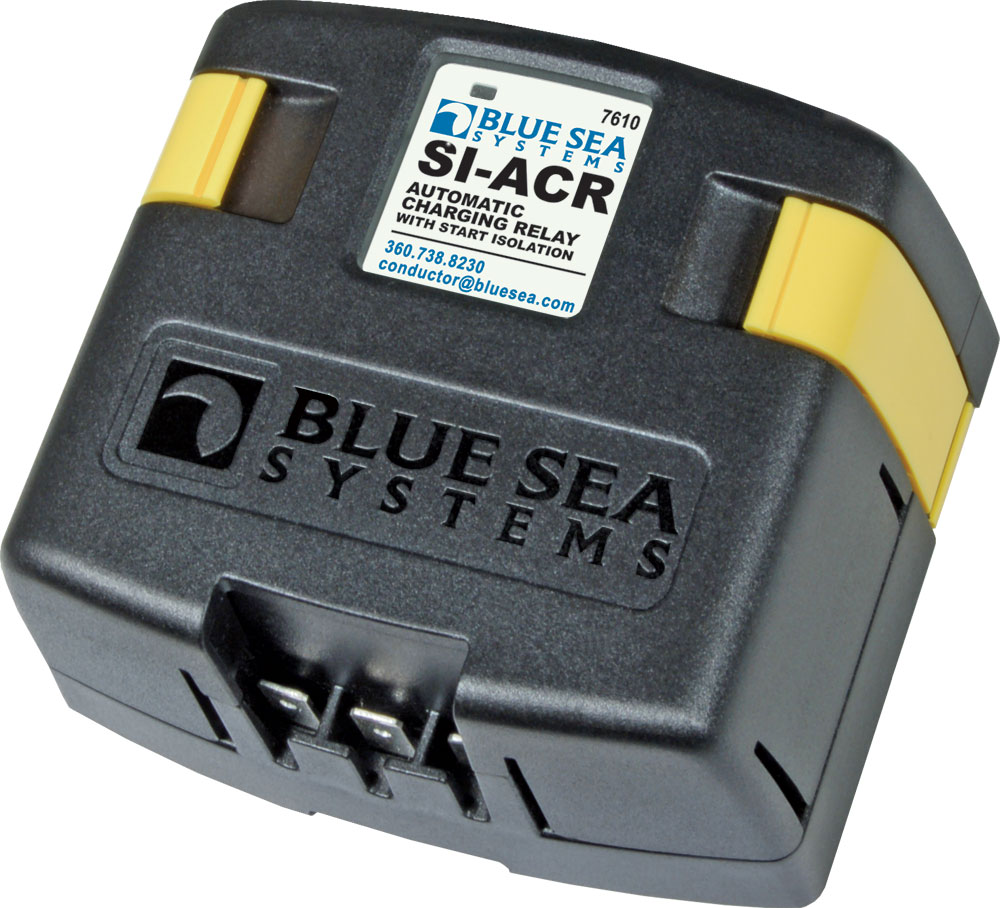
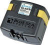
I have a Blue Sea ACR controlling the charging of both banks. The
ACR is mounted under the pilot berth in the compartment with the battery charger
and main circuit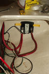 breaker panel. I follwed the instructions for the most part.
However, the ground line is 14 AWG (instead of 16 AWG) and I used the house line
post (the one on the left as a bus to connect the DC main (6 AWG). The
cranking battery line is 4 AWG, and the 5' run from house switch to the ARC is 2
AWG.
breaker panel. I follwed the instructions for the most part.
However, the ground line is 14 AWG (instead of 16 AWG) and I used the house line
post (the one on the left as a bus to connect the DC main (6 AWG). The
cranking battery line is 4 AWG, and the 5' run from house switch to the ARC is 2
AWG.
The wiring or house and cranking batteries are detailed in the Blue Sea
resources; article 57 reproduced below. The original is on the Blue Sea
site:
http://bluesea.com/viewresource/57. Also, see
http://bluesea.com/viewresource/58.
Automatic Charging Relay - An Alternative to Multiple Output
Charging Systems
What do you do when the number of battery banks on your boat
is greater than the number of charging outputs from your
system′s battery charger, and you want to provide a charge to
all batteries? How do you design a boat electrical system that
charges two battery banks without adding the cost of a dual
output charger? Instead of upgrading your charging system, or
installing a system with multiple outputs, install an automatic
charging relay (ACR). The cost of a charging system with
multiple outputs is considerably more expensive than one with
single output, making the installation of the ACR a less
expensive option.
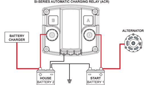
For example, consider a typical marine electrical system with
two battery banks, a battery charger with one output, and an
alternator. To charge both battery banks from your single output
charger, connect the ACR between the battery banks. Connect the
alternator to charge battery 1 (start battery), and connect the
charger to charge battery 2 (house battery). When the charger is
charging battery 2, the ACR will combine battery 2 and battery 1
for charging. When the alternator is charging battery 1, the ACR
will connect battery 1 and battery 2, and both batteries will be
charged. With the installation of the ACR, when at dock and
plugged into shore power, the charger is supplying a charge to
both battery banks; when the engine is running, the alternator
is charging both battery banks.
Similarly, if you are adding an auxiliary battery to power a
windlass, you can connect the auxiliary battery through an ACR
to a battery bank that is attached to a charger. In this way,
you are able to charge an additional battery bank without
upgrading the charger to one with multiple outputs.
The ACR automatically connects batteries during the charging
cycle and disconnects them under discharge.
When combined with Blue Sea Systems Dual Circuit Plus™ Battery
Switch (PN 5511e), the SI ACR model fully automates the charging
of two batteries. The combination of the Dual Circuit Plus™
Battery Switch and ACR provides a practical and less expensive
solution to manage:
- Isolated battery circuits
- Emergency parallel backup operation
- Automated charge management
Simply turn the battery switch to the ON position when
arriving on the boat, and turn it to the OFF position when
leaving. You no longer have to worry about which batteries are
charging or discharging.
Before replacing your charger or inverter/charger, consider
the benefits of an ACR; and for a fully automatic system, add a
Dual Circuit Plus™ Battery Switch.
|